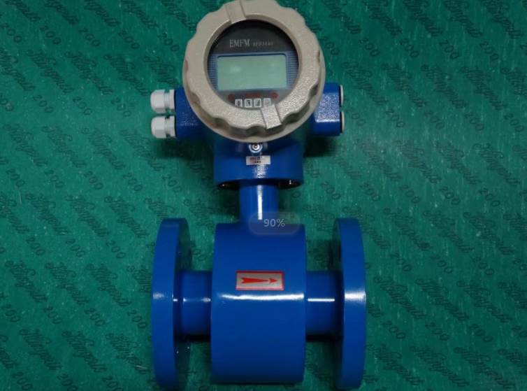
This product is suitable for flow measurement of industrial pipelines, channels, small rivers, and various conductive liquid measurements in environmental treatment. It is widely used in municipal water supply, steel, petroleum, chemical, power, industry, water conservancy, water administration, water resources and other departments.
1、 Technical parameters:
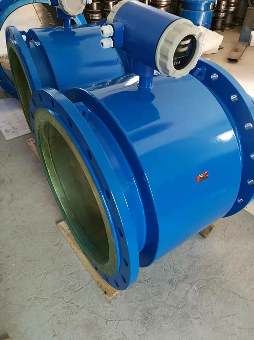
1. Measurable pipe diameter: Pipeline PTFE lining: DN10~DN600 Pipeline rubber lining: DN40~DN1200 Note: Special specifications can be customized
2. Accuracy level: Pipeline type: 0.5 level, 1.0 level
3. Temperature of the tested medium:
Ordinary rubber lining: -20 to+60 ℃; High temperature rubber lining: -20 to+90 ℃
PTFE lining: -30 to+100 ℃; High temperature PTFE lining: -30 to+180 ℃
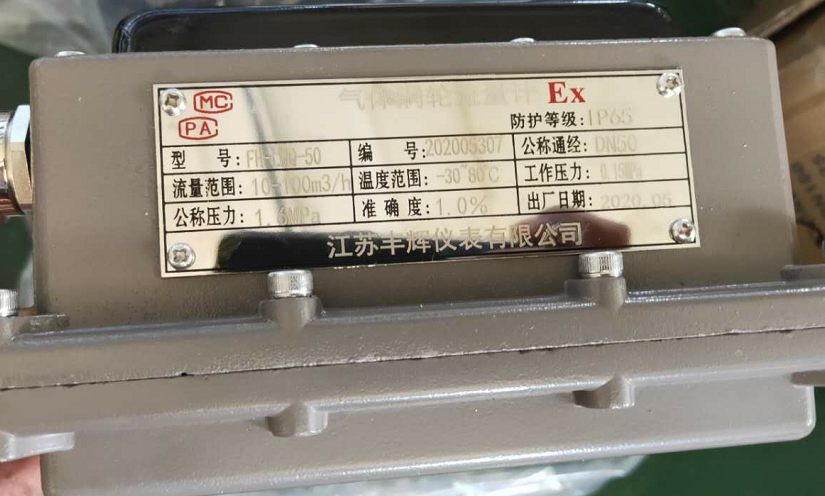
4. Rated working pressure:
DN10—DN65:2.5MPa
DN80—DN150:1.6MPa
DN200—DN1200:1.0MPa
5. Output signal and load resistance: 4-20mADC, 0-500 Ω
6. Electrode materials: including molybdenum stainless steel, titanium (Ti), tantalum (Ta), Hastelloy (HB), etc
7. Protection level: Submersible type: IP68, others: IP65
8. Power supply: 220VAC
9. Straight pipe length: Pipeline type: upstream ≥ 5DN, downstream ≥ 2DN
2、 Technical features:
1. Suitable for liquid flow detection with conductivity greater than 5 μ s/cm. Changes in conductivity do not affect changes in performance;
2. Electromagnetic flow meters have long-term high measurement accuracy and are actually not affected by the physical properties of the fluid;
3. Easy to put into operation, the flowmeter is automatically set within the range of 0-10m/s, without the need to change the measurement range;
4. All components in contact with the tested medium have good corrosion resistance and wear resistance, with a wide range of applications;
5. There are no movable parts or flow blocking components in the pipeline, and there is almost no additional pressure loss during measurement;
6. The measurement results are independent of physical parameters such as flow velocity distribution, fluid pressure, temperature, density, viscosity, etc.
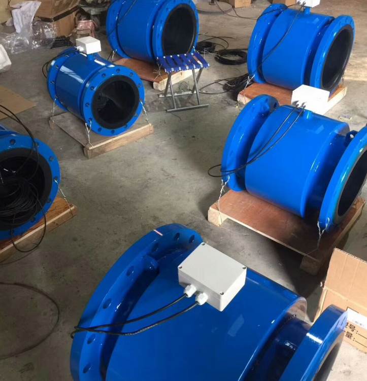
3、 Installation:
1. Electromagnetic flow meters should be installed at lower and vertically upward positions in horizontal pipelines, avoiding installation at ultra-high points and vertically downward positions in pipelines;
2. The electromagnetic flowmeter should be installed at the rising point of the pipeline;
3. When installing an open discharge pipeline, it should be installed at the lower part of the pipeline;
4. If the pipeline drop exceeds 5m, install an exhaust valve downstream of the sensor;
5. Electromagnetic flow meters should be installed with control valves and shut-off valves downstream of the sensor, rather than upstream of the sensor;
6. Sensors cannot be installed at the inlet and outlet of the pump, but should be installed at the outlet of the pump;
7. The method of installing an electromagnetic flowmeter in the measuring well.

陈超 18015125918